
Solar Water Pump Long-Shutdown and Restart Checklist

A solar water pump long-shutdown plan protects the pump, controller, photovoltaic array, pipework, well equipment, sensors, and stored commissioning data when a system will remain idle for weeks or months. Simply switching the controller off can leave water trapped in freeze-prone pipework, corrosion or sediment developing at the intake, connectors exposed to moisture, settings undocumented, and a future technician without a baseline. Restart should therefore be treated as a controlled recommissioning activity rather than an ordinary daily start.
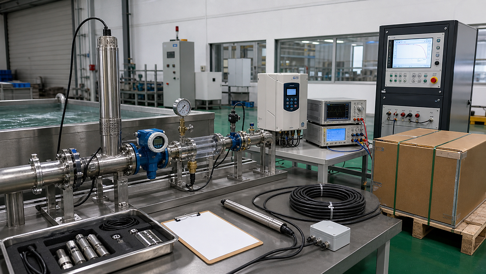
This guide addresses seasonal irrigation systems, livestock installations with alternate water sources, remote boreholes, temporary projects, and sites stopped for maintenance or ownership changes. Product-specific manuals, electrical isolation rules, local water requirements, and qualified personnel remain controlling. The visual used with this article is a concept illustration of pump-system testing; it is not proof of a specific model or field result.
Decide whether the pump stays installed or is removed
The first decision is the lay-up state. A submersible pump may remain in a borehole when water chemistry, minimum submergence, cable support, sediment risk, freezing, theft, access, and manufacturer instructions permit. A surface pump may need draining, cleaning, preservation, and dry storage. A portable unit may be removed with its controller, cables, and accessories as a controlled kit.
Record the reason for shutdown, expected duration, seasonal temperature, flood or drought risk, well status, water chemistry, sediment, site security, alternate supply, and responsible owner. Define who can isolate, inspect, energize, and authorize restart. An undefined shutdown often becomes an abandoned system with unknown condition.
The USDA NRCS technical note on solar-powered water pump systems emphasizes that each system has unique design constraints and that the design process must consider the interacting elements. Apply the same system view during lay-up: the pump, water source, hydraulic route, storage, PV supply, control, and environment cannot be preserved independently.
The U.S. Department of Energy's pump systems resources include guidance on effective maintenance, matching pumps to system requirements, surveying systems, and testing efficiency. Those resources support measured baseline comparison, but they do not replace the supplied pump and controller manuals.
Capture the last healthy operating baseline
Before shutdown, operate the system under a documented stable condition when safe. Record date, technician, weather, irradiance if measured, ambient and module temperature, static and pumping water level, tank level, discharge elevation, flow, pressure, controller input and output, motor current, operating frequency or speed if available, alarms, vibration, sound, leakage, and water appearance.
Save the controller parameter set, firmware identification, alarm history, runtime, start count, energy data, and communication configuration. The controller backup guide explains how to preserve and verify settings without assuming that every controller exports the same fields.
Photograph array condition, combiner or isolator positions, controller terminals, earthing and bonding, cable routes, wellhead, valves, gauges, filters, tank controls, and equipment labels. Link every image to the asset ID and date. A folder of unlabeled photos is not a baseline.
Shutdown sequence and energy control
Write a site-specific sequence from the approved manuals and electrical safety procedure. A general workflow is:
Notify users and confirm the alternate water arrangement.
Operate at a stable point and capture the final baseline before changing settings.
Stop the pump through the normal control path and save alarms before resetting anything.
Isolate all energy sources using the approved method, including PV, grid, battery, generator, control, and stored pressure where present.
Verify the safe state with suitable instruments and authorized personnel.
Close, open, vent, drain, or bypass valves according to the hydraulic preservation plan.
Protect exposed connectors, cable ends, sensors, and openings without trapping moisture.
Apply lockout, identification, inspection dates, and restart authorization controls.
PV modules remain energized in light. Covering modules, opening disconnects, or handling connectors requires the method specified by the system design and site procedure. Do not unplug DC connectors under load or improvise a short circuit to stop generation.
Hydraulic preservation plan
Map every low point, high point, dead leg, filter, pressure vessel, valve, exposed pipe, drain, check valve, and tank connection. State whether water remains, is drained, is flushed, or is treated. Freeze-prone sites need verified drainage or an engineered freeze-protection approach. A closed valve can isolate a section that appears drained while trapping water elsewhere.
For surface pumps, follow the manufacturer procedure for draining, cleaning, corrosion protection, seal condition, bearing or lubricant care, suction-line protection, and storage. Do not assume an empty casing is preserved; residual moisture, contaminants, or an open port can create damage.
For borehole systems, inspect the wellhead seal, cable support, rising main, check valves, pitless adapter or discharge head, vent, contamination barriers, and signs of movement. Record the pump setting depth and last measured water levels. If removal is required, plan safe lifting, cable and pipe support, cleanliness, identification, inspection, and storage before work starts.
PV array, controller, and instrumentation
Inspect modules for damage, contamination, vegetation, shading changes, loose structures, and animal activity. Record connector and cable condition without disturbing energized circuits unnecessarily. Protect controller ventilation paths while preventing pests, dust, and condensation. Do not seal a controller in plastic if that creates moisture retention or violates storage instructions.
Back up controller parameters and note every deliberate change made for shutdown. Label temporary jumpers, removed sensors, disconnected float switches, bypassed communications, and spare parts. A future restart must not depend on memory.
For gauges, flow meters, level sensors, weather instruments, telemetry, and data loggers, state whether they remain powered, are removed, are calibrated, or are stored. Preserve calibration due dates and configuration files. Replace batteries only under the device procedure, and avoid losing timestamps or accumulated data.
Long-shutdown inspection interval
Idle systems still change. Set an inspection interval based on climate, security, flooding, lightning, vegetation, corrosion, pests, water quality, and shutdown duration. The inspection sheet should include:
Locks, labels, barriers, fencing, enclosure seals, and evidence of unauthorized access.
Module glass, supports, clamps, cables, connectors, earthing, vegetation, and shading.
Controller enclosure, condensation, corrosion, pests, filters, ventilation, surge protection, and alarm state if energized.
Wellhead, water level where safely measurable, pipe supports, valves, drains, tank, leakage, and contamination barriers.
Stored pump, motor, cables, seals, accessories, desiccant where specified, and preservation date.
Storm, flood, lightning, construction, vandalism, or water-quality events since the previous visit.
Record observation, action, photograph reference, owner, due date, and closure. “No change” should mean the listed points were actually checked.
Restart readiness review
Before applying power, compare the current installation with the shutdown record and approved drawings. Resolve unauthorized wiring, replaced components, shifted pipework, new shading, changed water levels, blocked intakes, damaged cables, missing guards, open drains, temporary blanks, and expired inspection or calibration items.
Confirm the pump and controller still match the array, motor, hydraulic duty, cable length, sensor logic, and destination supply. Restore only the approved parameter file and document differences. Inspect polarity, insulation, earthing, protective devices, connectors, terminal condition, and enclosure integrity through qualified procedures.
On the hydraulic side, verify valve lineup, priming requirements, tank controls, pressure relief, check valves, air release, filters, pipe restraint, and available water. A surface pump must not be run dry while attempting to prime it. A submersible pump needs confirmed submergence and motor-cooling conditions.
Controlled recommissioning test
Use the commissioning test-sheet guide and compare results with the pre-shutdown baseline. A practical restart sequence is:
Record static water level, tank level, valve lineup, array condition, controller settings, instrument IDs, weather, and temperatures.
Energize controls under the approved procedure and capture faults before reset.
Prove tank, float, dry-run, pressure, remote-stop, and other permissives without unsafe bypasses.
Start at a controlled condition and observe voltage, current, frequency or speed, flow, pressure, sound, vibration, leakage, and water quality.
Increase duty only when the previous stage is stable and within model-specific limits.
Measure pumping water level, drawdown, delivered flow, head, and controller input under a comparable solar condition.
Prove normal stop, protective response, alarm transmission, data logging, and restart logic.
Record deviations, corrective action, final measurements, acceptance authority, and next inspection.
Do not declare a pump healthy because it turns. The acceptance result should show that the water source, hydraulic system, PV array, controller, motor, pump, sensors, and controls operate together at the required duty.
Example lay-up and restart record
Field: Asset identity; Shutdown record: Pump, motor, controller, array and sensor IDs; Restart evidence: Identity confirmed or deviation approved
Field: Hydraulic state; Shutdown record: Valves, drains, water level, tank and pipe condition; Restart evidence: Lineup restored, priming/submergence verified
Field: Electrical state; Shutdown record: Isolation points, parameters, alarms and cable condition; Restart evidence: Safe checks complete, settings restored, faults reviewed
Field: Preservation; Shutdown record: Cleaning, drainage, protection, storage and inspection interval; Restart evidence: Preservation removed and parts inspected
Field: Baseline; Shutdown record: Flow, head, water level, voltage, current and conditions; Restart evidence: Comparable measurements and explanation of differences
Field: Protection; Shutdown record: Float, dry-run, pressure, remote stop and alarm logic; Restart evidence: Functional results and event records
Field: Release; Shutdown record: Responsible owner, date, open actions and restrictions; Restart evidence: Authorized return to service
All numeric limits must come from the actual design and manuals. If a measurement was taken under a different solar resource, water level, valve position, or head, document the difference rather than treating it as equipment degradation.
Common restart failures
Frequent problems include starting with a closed discharge valve where not permitted, a drained suction line, blocked intake, insufficient submergence, reversed sensor logic, forgotten temporary jumper, stale parameter file, damaged connector, changed float level, seized surface-pump component, trapped air, sediment ingress, new pipe leak, and an array obscured by vegetation or soiling.
Investigate by system boundary. Save alarms and measurements before repeatedly cycling power. The preventive-maintenance checklist can continue the record after acceptance and help distinguish a startup defect from normal service deterioration.
Frequently asked questions
How long can a solar water pump remain shut down?
There is no universal duration. The permitted idle period and preservation method depend on the pump, motor, controller, seals, water chemistry, environment, freeze risk, storage condition, and manufacturer instructions. Define inspections rather than leaving the asset unattended.
Should a submersible pump be removed from the borehole for seasonal shutdown?
Not automatically. Review water chemistry, submergence, sediment, freezing, cable and pipe support, contamination control, security, access, expected duration, and the manufacturer procedure before deciding.
Can the controller simply be turned on after a long shutdown?
No. First inspect the array, wiring, protection, controller, settings, pump, hydraulics, sensors, water source, and temporary shutdown measures. Restart through a controlled recommissioning test.
Which measurements should be compared at restart?
Compare flow, head, static and pumping water levels, array voltage and current, controller output, motor current or speed where available, alarms, sound, vibration, leakage, and the environmental conditions that affect those values.
Contact RUTANPUMP
For solar water pump shutdown planning, recommissioning, model selection, controller settings, field documentation, OEM supply, and distributor support, contact RUTANPUMP / Wenling Jingzhan Mechanical & Electrical Co., Ltd.
Email: sales@rutanpump.com
WhatsApp / WeChat: +86 18267835331 | Tel: +86 (0576) 86322398
Website: https://www.rutanpump.com/ | Send an inquiry


留言