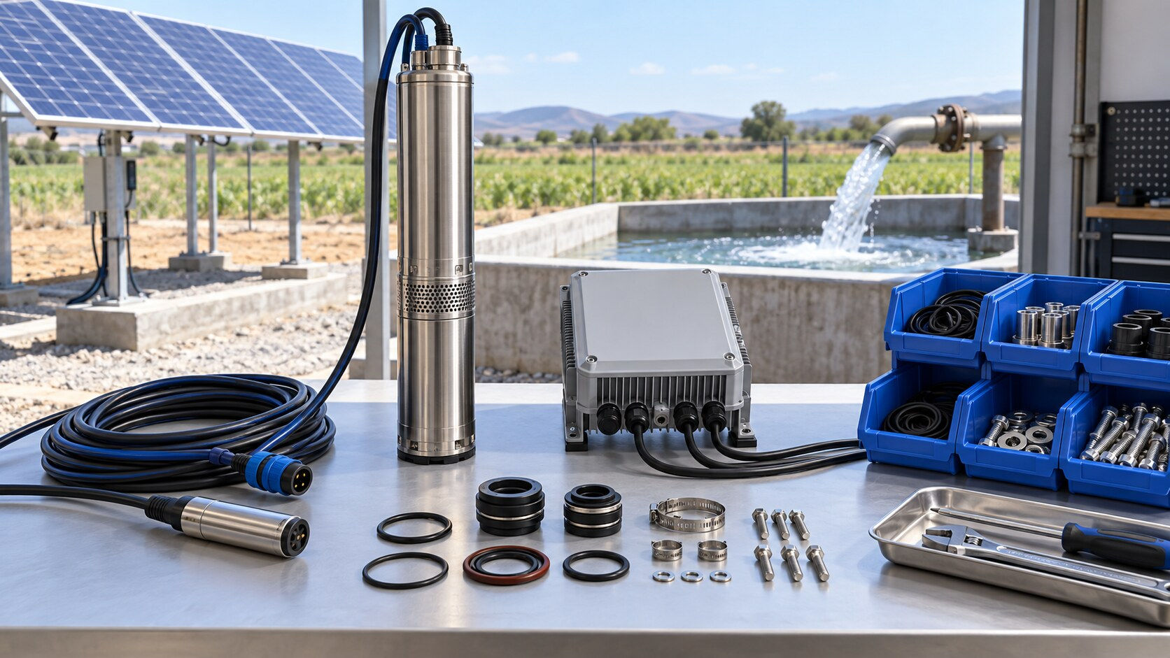
Solar Pump Spare Parts Planning: Criticality, Stocking, and Replacement Acceptance

A solar water pump can stop for a minor component that costs little compared with the lost water delivery. The practical question is not whether a distributor can stock every part. It is which parts create unacceptable downtime, which items can be diagnosed reliably in the field, and how a replacement is verified before the system returns to service. A solar pump spare parts list should therefore be based on system criticality and evidence, not on a generic catalog bundle.

This guide gives installers, farm operators, and distributors a method for building a site-specific spare-parts plan. It covers component identification, failure consequence, lead time, storage conditions, replacement records, and functional acceptance. The method applies to off-grid photovoltaic pumping systems, but every actual selection must follow the pump, controller, motor, cable, sensor, and array documentation for the installed model.
Map the installed system before choosing spares
Begin with an as-built asset register. Record the pump model, motor rating, controller model and firmware where applicable, PV array configuration, cable size and length, pipe arrangement, non-return valve, level sensors, protection devices, and communication accessories. Photograph nameplates and connector arrangements. A spare is useful only when it matches the installed interface and operating envelope.
IEC 62253:2011 describes design qualification and performance measurements for stand-alone photovoltaic pumping systems. NREL's Best Practices for Operation and Maintenance of Photovoltaic and Energy Storage Systems also treats spare-parts inventory as part of organized O&M. These sources support a systems approach: replacing one component without checking its electrical, hydraulic, and environmental context can create a second fault.
Classify parts by consequence and diagnostic certainty
Use four questions for each component:
Does its failure stop all water delivery or only reduce performance?
Can field staff identify the fault without substituting a known-good part?
What is the replenishment lead time, including customs and seasonal transport?
Can the item be stored without degradation, contamination, or firmware obsolescence?
The answers create a more useful classification than price alone.
Spare category: Mission-critical module; Typical examples: Compatible controller, pump/motor assembly; Stocking logic: Consider local stock where downtime and lead time are high; Main acceptance evidence: Exact model match, settings backup, electrical and flow checks
Spare category: High-failure exposure; Typical examples: Level sensor, float switch, surge device, connector, cable termination kit; Stocking logic: Stock based on exposure and service history; Main acceptance evidence: Wiring continuity, insulation condition, functional trip or signal check
Spare category: Wear or sealing item; Typical examples: Approved seal, O-ring, gasket, check valve service part; Stocking logic: Stock only with verified material and dimensions; Main acceptance evidence: Part identity, clean installation, leak test
Spare category: Installation consumable; Typical examples: Correct cable gland, ferrule, heat-shrink, fastener; Stocking logic: Maintain controlled field kit; Main acceptance evidence: Size, material, crimp or torque method
Spare category: Diagnostic tool or adapter; Typical examples: Programming lead, current clamp, pressure gauge adapter; Stocking logic: One controlled kit per service team; Main acceptance evidence: Calibration or function check and compatibility
Do not assume a visually similar controller or sensor is interchangeable. Voltage limits, motor control method, connector pinout, firmware, sensor logic, and environmental rating may differ.
Calculate a stocking level with explicit assumptions
A simple planning model can prevent both shortages and excessive inventory. For each item, estimate:
**Reorder quantity = expected demand during replenishment lead time + safety quantity - usable stock on hand.**
Suppose a distributor supports 60 similar pump systems. Based on documented service records, a particular level sensor has an annual replacement rate of 5 percent. Replenishment takes 12 weeks. Expected demand during lead time is approximately 60 × 0.05 × 12/52 = 0.69 units. A policy of one additional unit for uncertainty would suggest a reorder point near two usable sensors. This is only a planning example, not a reliability claim for any RUTANPUMP product.
Repeat the calculation using your own installed base, observed demand, seasonality, transport risk, and service target. For high-value pump assemblies, a regional shared spare or loan unit may be more economical than one unit at every site.
Verify compatibility before the part enters stock
Receiving inspection should prevent a wrong spare from becoming a delayed field failure. The record should include:
Purchase order and supplier part number.
Compatible pump, motor, or controller models.
Electrical ratings and connector or terminal arrangement.
Mechanical dimensions, thread, seal material, and direction of flow where relevant.
Firmware or parameter-file dependency.
Manufacturing or batch code and receipt date.
Storage conditions and any shelf-life information supported by the manufacturer.
Photograph of the received item and label.
For a controller, archive the approved parameter set separately. A replacement controller shipped with default settings may run the motor incorrectly or fail to protect the water source. For cable and connectors, control the conductor size, insulation type, sealing method, and tooling rather than purchasing by appearance.
Store spares so they remain usable
Inventory count does not equal service readiness. Keep electronic modules in clean, dry packaging and protect terminals from contamination and electrostatic handling risks stated by the manufacturer. Seal kits should be protected from sunlight, heat, oils, and deformation. Cable glands and connectors should remain paired with their seals and installation instructions.
Apply first-in, first-out where aging matters, but do not install an older revision automatically. Before issue, confirm that firmware, connector, label, and approved substitution status still match the field asset. Quarantine parts with damaged packaging, corrosion, cracked insulation, missing identity, or uncertain compatibility.
Use a controlled replacement procedure
A spare part should not be used as the first diagnostic step unless the troubleshooting plan calls for substitution. Record baseline evidence before removing the original component.
Make the site electrically and mechanically safe under the applicable procedures.
Record controller messages, array voltage, operating current, water level, pressure or head indicators, and observed flow condition.
Inspect cable, connectors, pipework, filters, valves, and sensor state for external causes.
Confirm the diagnosis against the manufacturer's manual or an approved fault tree.
Verify the spare's part number, revision, settings, and physical condition.
Photograph wiring and orientation before disassembly.
Install with the specified tooling, sealing, torque, polarity, and strain relief.
Retain the removed part with a fault tag if analysis or warranty review is required.
This sequence helps distinguish a failed component from a system condition such as insufficient irradiance, low source water, excessive dynamic head, blocked pipework, unstable array voltage, or damaged cabling.
Accept the repaired system with measured evidence
The replacement is not complete when the equipment powers on. Use a staged acceptance check appropriate to the system and site.
Check stage: Visual and identity; Record: Part number, orientation, cable support, sealing; Acceptance basis: Approved drawing and manufacturer instructions
Check stage: De-energized electrical; Record: Continuity, polarity, insulation checks where specified; Acceptance basis: Site procedure and equipment documentation
Check stage: Start-up; Record: Array voltage, controller status, motor behavior; Acceptance basis: Approved operating sequence
Check stage: Hydraulic response; Record: Flow observation, pressure or head indicator, leaks; Acceptance basis: Site duty point and baseline record
Check stage: Protection; Record: Dry-run or level input response when a safe test is defined; Acceptance basis: Approved control logic, not an improvised trip test
Check stage: Stabilized run; Record: Current, voltage, noise, vibration, temperature observations; Acceptance basis: Manufacturer limits and comparable baseline
Check stage: Closeout; Record: Settings backup, replaced-part record, stock balance; Acceptance basis: Maintenance system requirements
Do not invent pass limits. Use values from the installed system design, equipment manual, commissioning record, and site risk assessment. If no baseline exists, record the new measured condition without presenting it as proof of full design performance.
Manage the removed part and update the forecast
Label the removed component with site, date, operating hours if known, symptoms, measurements, and technician. Decide whether it is scrap, repairable, under warranty, or held for engineering review. The solar pump warranty-return workflow provides a chain-of-custody structure for parts requiring supplier analysis.
Each replacement should update the spare-parts forecast. Separate confirmed failures from precautionary swaps and installation damage. A rising demand signal may indicate an environmental or system-design issue rather than a weak component. The preventive-maintenance checklist helps capture the surrounding conditions, while a distributor pilot-batch field trial can establish service evidence before a large rollout.
Spare-parts request template
When requesting a quotation, provide:
Installed pump and controller model, serial or batch identifier, and purchase date.
PV array voltage configuration and motor rating.
Exact failed or suspected part with photographs.
Connector, cable, thread, and dimensional details.
Controller message and measured electrical or hydraulic evidence.
Quantity of supported systems, destination, desired service level, and current stock.
Requirement for firmware, parameter file, tooling, seals, or installation instructions.
This information allows a supplier to check compatibility before shipment. It also reduces the risk of using emergency freight for an item that cannot be installed.
Authoritative references
Frequently asked questions
Which spare should a remote solar pump site stock first?
Prioritize by downtime consequence, diagnostic certainty, replenishment lead time, compatibility, and storage stability. The answer may be a sensor or connector kit rather than the highest-value component.
Can a controller with the same power rating replace the original?
Not automatically. Confirm voltage limits, motor control method, connector pinout, sensor logic, protection functions, firmware, parameter set, and environmental requirements.
Should the original faulted part be discarded after replacement?
Keep it with a traceable fault tag when warranty, repair, or root-cause analysis is required. Record symptoms and measurements before removal so the evidence is not lost.
What proves that a replacement was successful?
A documented acceptance sequence covering identity, wiring, sealing, start-up, hydraulic response, protection logic where safely testable, stabilized operation, and closeout records provides stronger evidence than a simple power-on check.
Contact RUTANPUMP
For a model-specific solar pump spare-parts review, send the installed equipment identity, photographs, measured symptoms, supported-system count, destination, and desired service level through the RUTANPUMP contact page.
RUTANPUMP / Wenling Jingzhan Mechanical & Electrical Co., Ltd. Email: sales@rutanpump.com WhatsApp/WeChat: +86 18267835331 Telephone: +86 (0576) 86322398

留言