
Solar Pump Factory Acceptance Testing: Protocol, Data and Release Gates

已更新:8月9日
A solar pump factory acceptance test, or FAT, is a pre-shipment verification that the production-intent pump, motor, controller, sensors, cables, interfaces, documents, and packaging match the approved order and perform within agreed limits. It is not a ceremonial run. The protocol must identify the tested units, calibrated instruments, hydraulic conditions, DC source, controller settings, expected results, tolerances, deviations, and release authority before the witness arrives.
A well-designed FAT reduces integration surprises but does not replace site acceptance testing. The factory can reproduce pump-system behavior under controlled water, piping, electrical, and environmental conditions; it cannot reproduce the real borehole yield, field pipe route, installation workmanship, local irradiance, or every water-quality effect. The contract should define what the FAT proves, what remains for site commissioning, and which changes trigger renewed testing.
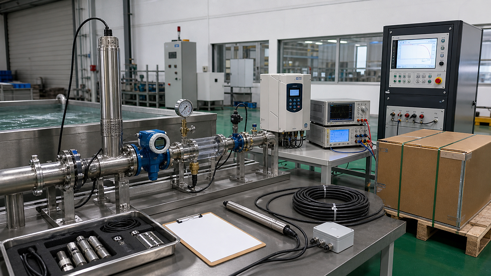
1. Freeze the test configuration before the FAT
The FAT specimen must represent the offered system. Record pump model and serial number, motor rating, controller model, hardware and firmware revision, parameter file checksum, cable type and length, level sensor, flow and pressure instruments, valves, accessories, labels, manuals, and packaging revision. If a substitute component is used for convenience, the report must identify it and explain what evidence covers the production item.
Approved purchase specification, hydraulic duty points, pump curve, total dynamic head basis, daily water requirement, and controller operating window.
Bill of materials and drawings for pump, motor, cable joint, controller, PV input, sensors, control enclosure, and supplied accessories.
FAT procedure with test sequence, instrument list, stabilization rule, acceptance limits, witness and hold points, safety controls, and report template.
Sampling plan stating whether every unit, one unit per model, or a statistically defined sample is tested and how the witness specimen is selected.
Open-deviation list showing owner, containment, retest requirement, customer disposition, and shipment-blocking status.
The official IEC 62253 publication page describes design qualification and performance measurements for stand-alone photovoltaic pumping systems, including indoor measurements with a PV generator simulator or outdoor measurements with a real PV generator. It applies to motor-pump sets connected directly or through a converter. The buyer should state whether IEC 62253 is contractually applicable rather than assuming every factory demonstration follows it.
2. Verify the hydraulic test bench and measurement chain
Before testing the product, verify the bench. The loop should provide stable flow and head over the required range, adequate straight pipe lengths or validated meter installation, controlled water condition, air removal, pressure tapping, throttle control, and safe pump cooling. Instruments need suitable range, resolution, calibration status, and uncertainty. Record water temperature, suction condition, datum elevations, atmospheric pressure where relevant, and the exact definition of head and input power.
ISO 9906:2012 specifies hydraulic performance acceptance tests for rotodynamic pumps at manufacturer or laboratory test facilities and defines acceptance grades. It can apply to the pump alone or with specified upstream and downstream fittings. Do not quote an ISO grade unless the contract identifies it and the bench, procedure, tolerances, and result evaluation actually follow the relevant requirements.
Illustrative duty-point calculation
Suppose the purchase duty is 6.0 m3/h at 55 m total head. During a stabilized run, the corrected measurements are 6.12 m3/h and 54.6 m. Flow deviation is (6.12 - 6.00) / 6.00 x 100 = +2.0 percent. Head deviation is (54.6 - 55.0) / 55.0 x 100 = -0.73 percent. These numbers are not automatically a pass: compare them with the contract's selected acceptance grade, measurement uncertainty, permitted combinations, and the agreed evaluation method.
If expanded uncertainty for flow is +/-0.9 percent and the contractual upper flow limit is +2.5 percent, a +2.0 percent result is close to the boundary. The parties should already have agreed whether guard bands apply and how uncertainty affects conformity. Changing the rule after seeing data invites disputes. The report should retain raw readings, corrections, stability evidence, instrument IDs, calculation sheet, and plotted point.
3. Test more than one operating point
A single duty point can hide an incorrect impeller, motor, controller parameter, or unstable curve. Select points that represent the approved operating envelope: shutoff or minimum-flow behavior only where safe and permitted, low-flow/high-head, duty point, high-flow/low-head, and any project-specific limit. For solar operation, repeat relevant points across the controller's DC input window or simulated irradiance conditions so startup, MPPT behavior, derating, and shutdown are visible.
Record flow, suction and discharge pressure, total head, pump speed or controller frequency, DC voltage and current, motor-side values where safely measurable, input power, water temperature, and steady-state time.
Plot measured points against the approved curve and identify corrections or differences in test configuration.
Check for abnormal noise, vibration, leakage, unstable control, cable heating, repeated restart, cavitation indications, and protective derating.
Confirm that the tested motor-pump-controller combination is the ordered configuration, not three separately approved catalog components.
Retain trend data through startup, stabilization, step changes, and shutdown instead of reporting only hand-selected steady values.
The U.S. Department of Energy pumping systems sourcebook explains pump and system curves, operating points, multiple-pump arrangements, and system-level efficiency opportunities. Its practical lesson for FAT planning is that a measured pump point must be interpreted against the system duty. A strong laboratory result at the wrong head or flow does not validate the buyer's application.
4. Verify PV input and controller behavior
Use a documented programmable DC or PV-array simulator when indoor testing is intended to represent solar behavior. Define the simulated array open-circuit voltage, maximum-power voltage, current limit, temperature basis, ramp profile, and controller input limits. Confirm polarity protection, startup threshold, MPPT acquisition, response to irradiance ramps, low-power cycling, overvoltage handling within the approved test method, controlled shutdown, and restart after power restoration.
Controller parameters are part of the accepted product. Export and archive the parameter set before the FAT, compare it with the approved baseline, and include a readable schedule in the report. If firmware or parameters change after witnessed testing, assess the impact and repeat affected cases. The system should not leave the factory with a successful report tied to a different build than the shipped controller.
5. Run protection and interface sequences safely
Protection tests need defined stimuli and expected timing, state, alarm, output, and recovery. Simulate dry-run using the approved method rather than damaging the pump. Challenge tank-full input, low-water input, sensor open or short where supported, motor overload or blocked condition through a safe emulator or controlled method, controller overtemperature input, communication loss, and emergency stop or external interlock. Record both trip and restart behavior.
Dry-run: initial flow and load, injected condition, detection time, stop response, alarm, restart delay, retry count, and manual-reset rule.
Tank-full: contact logic, debounce, controlled deceleration, stopped state, lower-level restart condition, and behavior after input wire fault.
DC power variation: ramp down, undervoltage stop, absence of contactor chatter, retained parameters, and deterministic morning restart.
Communication: valid messages, timeout, invalid frame handling, local protection independence, diagnostic code, and recovery after bus restoration.
Changeover or multiple sources: break-before-make logic, interlocks, valve state, crossflow prevention, and source-specific settings.
For coordinated architectures, the duty-standby solar pump changeover guide provides a sequence and commissioning matrix. Projects using more than one water source should also review the multiple-borehole solar pump design guide. A single factory rig cannot validate borehole recovery, so the site test must verify source-specific dry-run thresholds and sustainable abstraction.
6. Build the FAT matrix and release gate
Each FAT row should contain: requirement ID; subsystem; specimen and serial; starting state; procedure step; commanded input; expected value or state; tolerance; instrument; measured result; pass, fail, or not tested; evidence file; deviation ID; retest result; witness; and approval. This structure prevents photographs and narrative comments from replacing measurements.
Identity and workmanship: models, ratings, construction, cable, connectors, rotation, labels, fasteners, supplied accessories, and visible defects.
Hydraulic performance: agreed points, curve comparison, stability, power, temperature, uncertainty, and any correction.
Electrical and control: PV input window, startup, MPPT response, current limiting, parameters, firmware, I/O, and communications.
Protection: dry-run, tank level, overload, sensor faults, power interruption, alarms, latching, delay, reset, and safe recovery.
Documentation: approved drawings, wiring diagram, pump curve, parameter list, manuals, test certificates, packing list, and serial traceability.
Packaging and shipment: preservation, cable bend radius, terminal protection, moisture control where specified, accessory segregation, markings, and final release.
The shipment release gate should require all hold points passed, calibrated instruments in date, reports complete, deviations formally dispositioned, retests closed, production configuration matched, and packing inspection accepted. A concession must identify the affected units, requirement, risk, temporary control, customer authorization, and expiry. Verbal acceptance or an unsigned chat message is not a durable release record.
FAT and site acceptance should share a handover dataset. The factory report provides baseline flow, head, power, controller settings, alarms, and identity. Site teams then add actual static and dynamic water levels, pipe losses, tank elevation, PV string measurements, installed flow and pressure, earthing, sensor positions, and daily yield. This makes disagreement diagnosable rather than a contest between unrelated measurements.
Frequently asked questions
What should be included in a solar pump factory acceptance test?
Include configuration and serial verification, calibrated hydraulic duty-point tests, PV-controller operating tests, protection and interface sequences, firmware and parameter records, documentation review, packaging inspection, deviation closure, and a signed shipment release.
Does a successful FAT guarantee site water output?
No. FAT verifies the agreed system under controlled factory conditions. Site output also depends on borehole yield, dynamic water level, pipe losses, elevation, irradiance, array installation, water quality, sensors, and commissioning. These require site acceptance evidence.
Who should approve the FAT procedure?
The buyer and supplier should approve the procedure, acceptance limits, measurement and uncertainty rules, sample selection, witness points, deviation process, and release authority before testing begins.
Contact RUTANPUMP
For solar water pump selection, FAT planning, OEM requirements, drawings, samples, test documentation, and project quotations, contact RUTANPUMP / Wenling Jingzhan Mechanical & Electrical Co., Ltd. Send the hydraulic duty, water source, PV basis, controller interfaces, quantity, destination market, required standards, witness plan, and delivery schedule.
Email: sales@rutanpump.com. WhatsApp / WeChat: +86 18267835331. Tel: +86 (0576) 86322398. Website: www.rutanpump.com.

留言